1. Determining of your system specifications and conditions
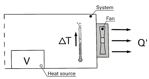
Determine the temperature rise inside your system and obtain the total heating value inside your system on the basis of its inputs and outputs.
Example
V : Total heating value of your system (W) = 100 (W)
△T : Inside temperature rise (K) = 15 (K)
2. Calculating the Required Air flow for Cooling
After the equipment specifications and conditions of your system have been determined, calculate required air flow to meet the conditions.
(Note that the formula shown below only applies when the heat radiation is performed only by cooling air from the fan.)
Example
Q’: Motion air flow (m³/min)
Q’ = V / (20 × △T) = 100 (W) / (20 × 15 (K)) ≈0.33 (m³/min)
3. Selecting the Fan
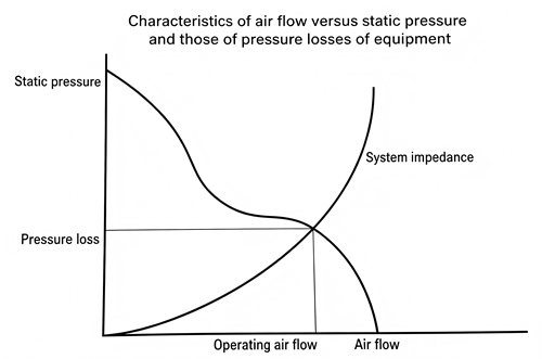
After the motion air flow has been calculated, select an appropriate fan motor based on the value. The motion air flow when the fan motor is actually mounted in your system can be obtained using the air-flow-static pressure characteristics curve and system impedance. However, the system impedance cannot be measured without a measuring equipment, so fan with 1.5 to 2 times higher air flow than the actual maximum air flow should be selected (operating air flow is one-third to two-thirds of maximum air flow).
Example
Q: Maximum air flow (m³/min)Q’ = Q × 2/3Q = Q’ × 3/2 = 0.33 × 3/2 ≈ 0.5 (m³/min)
∵ 1 CFM=0.0283(m³/min)
∴ 0.5 (m³/min)≈18 CFM
22 CFM≈0.62 (m³/min)
Next, in case that you select a fan having an air flow of 0.5 (m³/min) or more and an appropriate size for the space inside your system.
For example, if you need a fan of 80mm square, 25mm thickness and 100V, you should select is JA8025HB1(or HS1) (maximum air flow = 22 CFM).
4. Confirming the Selected Fan
Calculate the temperature rise inside your system when your system having 100 (W) of total heating value is forcefully cooled down by a JA8025HB1(or HS1) fan.
Example
Q’ = Q × 2/3 = 0.62 × 2/3≈ 0.41 (m³/min)△T = V / (20 × Q’) = 100 (W) / (20 × 0.41 (m³/min)) ≈ 12.2 (K)
From the above, the temperature rise inside your system is calculated as 12.2 (K).Since the value obtained from the above equation is only a rough target, final fan selection should be based on your actual installation test
Conversion Table
Characteristics calculation method and description
Measuring air flow and static pressure
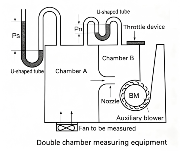
It very difficult to measure air flow and static pressure.In fact,the performance curve may vary greatly according to the type of measuring equiment.The commonly-used type of measuring equiment is a wind tunnel using a pitot tube. We uses a very precise method using double chamber equipped with many nozzles.Q = 60A v̄ (A)
where
Q = air flow (m³/min)
A = cross sectional area of nozzle = (π/4)D² (m²)
D = nozzle diameter
v̄ = average air flow velocity of nozzle = sqrt( 2g * Pn / γ ) (m/sec)
γ : Air specific gravity (kg/m³)
(γ = 1.2kg/m³ at 20℃, 1 atmospheric pressure)g = acceleration of gravity = 9.8 (m/sec²)
Pn = differential pressure (mm H₂O)
Ps = static pressure (mm H₂O)The measuring equipment using double chamber is method to be calculated from air flow goes through nozzle and differential pressure between pressure of inside of chamber (Ps) and atmospheric pressure by measuring differential pressure between air intake and exhaust of nozzle (Pn).
Reliability and Expectancy
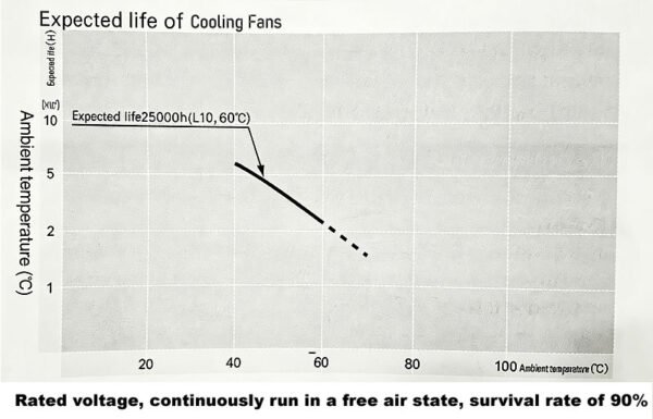
A fan generally cools itself as well . The temperature rise of the motor is relatively low and the temperature rise of the grease in the ings is also low , so expected life is longer than general some either motors . Since the service life of bearings is a theoretical value that applies when they are ideally lubricated , the life of lubricant can be regarded as expected life of the fan . The expected life of a cooling fan used at an ambient temperature 60℃ is 25,000 hours . When the measurement conditions are :L10( the remaining product life in the lifespan test is 90%), with an atmospheric temperature of 60degrees, at the rated voltage and with continuous free air . The right table indicates the relationship between ambient temperature and expected life estimated on the basis of our life tests and same other tests conducted by Sanyo Denki . An accelerated life test is conducted on the basis of the concept that the expected life halves as the ambient temperature rises by about 15°℃( within the operating temperature range of lubricant .)
Bearing Type and life expectancy:
Sleeve Bearing:30,000 hrs continuous operating under25℃ 65%RH
Dual Ball Bearing:50,000 hrs continuous operating under25℃ 65%RH
Noise Characteristics
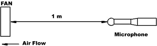
Noise is average value that measured at 1 meter away from air intake side of fan that is suspended on special frame in anechoic chamber (as per EN ISO 3743‑2:2019)