AIR QUALITY · APPLICATION ENGINEERING
Fans for Air Quality Monitoring & Purification
Controlled airflow for indoor monitors, vehicle cabins and portable air-quality equipment.

Air Quality Across Everyday Spaces
People move between homes, offices, vehicles and outdoor environments throughout the day. Dust, traffic emissions, pollen and volatile compounds create different monitoring and ventilation challenges in each space. Equipment designers need to consider the pollutants of interest, the air path and the conditions in which a device will operate.
IAQ means indoor air quality. AQI, or Air Quality Index, is a way to communicate air-quality conditions using a defined reporting method. A fan does not measure pollutants or calculate an index: the sensing hardware, calibration and reporting algorithm perform those tasks.
Two Airflow Duties: Sampling and Purification
Sensor sampling
Where the sensor design calls for forced airflow, the fan brings a representative sample into the sensing chamber. Follow the sensor manufacturer’s specified flow range, orientation and inlet arrangement. Some sensors use diffusion or an integrated air mover and do not require an added fan.
Filter and ventilation airflow
A purifier needs airflow through its filter or treatment stage at the installed pressure. Filter loading changes resistance over time. Compare the fan’s P–Q curve with the complete air path, then verify performance with the selected filter installed.
Stable fan speed can support repeatable sampling, but RPM alone does not establish flow or measurement accuracy. Leaks, inlet restrictions, contamination, temperature, humidity and sensor calibration also matter. Avoid directing the purifier’s cleaned outlet straight into a sensor intended to sample room air.
See the fan P–Q curve guide for operating-point selection and the fan selection guide for mechanical and electrical requirements.
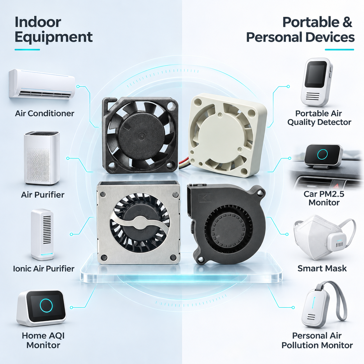
Applications in Three Environments
Indoor equipment
Home air purifiers, IAQ monitors, ventilation equipment and air-conditioning sensor modules can use compact air movers for sampling, electronics cooling or localized circulation. Specify a low-noise operating point and isolate vibration from the enclosure and sensing chamber.
In-car systems
Cabin air-quality sensors and compact car purifiers need to fit limited installation space. Check vibration, temperature, connector retention and the electrical supply presented to the fan. A nominal vehicle voltage does not by itself demonstrate compatibility with automotive supply transients.
Outdoor and portable devices
Handheld monitors and battery-powered sampling equipment place emphasis on size, power consumption and inlet protection. Evaluate moisture, dust, orientation and maintenance access. Wearable or assisted-airflow devices require separate system-level safety and performance assessment.
JyFan Models to Review
Use these compact product families as starting points for an engineering review. Confirm the exact model drawing, voltage, airflow curve, bearing and available control functions before selecting a sample.
| Model / family | Potential design role | What to verify |
|---|---|---|
| JF1503 · JF015 family | Space-limited sampling or miniature equipment airflow | Available clearance, starting behavior and sensor flow requirements |
| JF20 · JF020 family | Compact axial airflow for portable monitors and sensor enclosures | Frame depth, voltage, noise and installed air path |
| JB30 · JB030 family | Directed airflow in compact ducts or sensing assemblies | Outlet geometry and airflow at the required pressure |
| JB5015 · JB050 family | Blower airflow for compact filter paths or equipment ventilation | Filter resistance, power budget and acoustic behavior |
For measured results from one evaluated blower sample, see the 5015 DC blower performance test. Those results apply to that sample and its stated test conditions.
Specify Speed Stability, Noise and Environmental Protection
Discuss a compact format, low power consumption and low vibration with JyFan, then verify the proposed configuration in the finished equipment. PWM speed control, FG tachometer feedback and RD status signals can support host monitoring where available. Ask for interface limits and behavior at low speed.
If your design requires a speed tolerance within ±15%, include the target RPM, supply range, temperature and measurement conditions in the inquiry. JyFan can review feasibility for the selected configuration. This is an application requirement to confirm, rather than a guaranteed specification across all listed models. Speed tolerance also differs from speed fluctuation during operation; neither directly guarantees sensor accuracy.
For moisture or dust exposure, review environmental protection options and obtain the selected model’s documented rating and test conditions. Protection of the motor does not automatically protect the sensor inlet, connector or complete device. Continuous-duty service life likewise depends on bearing, temperature and operating conditions.
Validate the Complete Device
- Define the sensor’s flow requirements and the purifier’s separate airflow target.
- Test with the intended inlet, duct, filter and outlet installed.
- Record sample response, fan speed, current, noise and vibration under representative conditions.
- Check battery or supply variation, filter loading and environmental exposure.
- Document the accepted sample, configuration and test conditions before production.
A fan moves air; pollutant removal depends on the selected treatment technology. Ionization and personal-protection claims need their own evaluation. Some ionizers can produce ozone, so assess emissions and intended-use requirements at device level.
Technical References
- U.S. EPA: Air Sensor Technology and Indoor Air Quality
- U.S. EPA: Siting and Installing Air Sensors
- U.S. EPA: Ionizers and Other Ozone-Generating Air Cleaners
Discuss Your Air-Quality Device
Send the sensor flow requirement, drawing, voltage, pressure, noise target and expected duty cycle.
Request Samples & Pricing · Explore DC Fans & Blowers · All Applications