Original test case · JB501505L
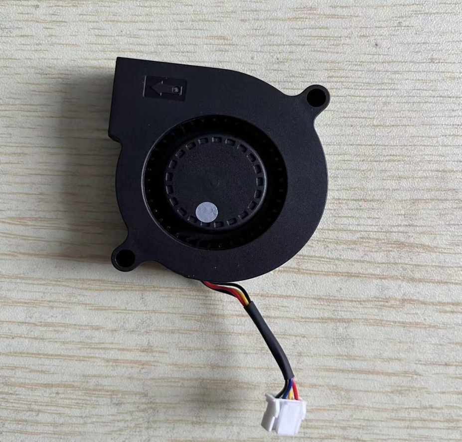
5015 DC blower: measured airflow, pressure & noise
A practical engineering reference for a 50 × 50 × 15 mm, 5 VDC blower used in PM2.5 sampling and compact equipment. Review the operating conditions, eight-point PQ data and product specifications before selecting a sample.
Measured results at a glance
2.43 CFM
At zero static pressure; approximately 4.13 m³/h.
2.31 mmH₂O
At zero airflow; approximately 22.7 Pa.
0.28–0.32 W
Across the eight recorded operating points.
20.20 dBA
At 1 m, with 15 dBA background noise.
These are measurements for the single sample and conditions documented in the report. Maximum airflow and maximum pressure are different endpoints on the curve; they do not occur simultaneously. Source: §§3–4.
Test conditions
The source report describes air-performance testing in JyFan’s laboratory using a wind-tunnel test system under AMCA 210.
| Parameter | Recorded condition |
|---|---|
| Sample | JB501505L; 1 unit |
| Method stated in source | AMCA 210 wind-tunnel air-performance test |
| Ambient temperature | 26.5 °C |
| Relative humidity | 45.6% RH |
| Atmospheric pressure | 756.5 mmHg |
| Speed recorded | 3309 RPM at all eight operating points |
| Voltage recorded | 4.7–4.9 VDC; nominal test condition 4.8 VDC |
Use the PQ curve together with your enclosure or duct resistance to determine the installed operating point.
Pressure–airflow curve and measured data
| Point | Static pressure (mmH₂O) | Airflow (CFM) | Speed (RPM) | Current (A) | Power (W) | Voltage (VDC) |
|---|---|---|---|---|---|---|
| 1 | 2.31 | 0.00 | 3309 | 0.06 | 0.28 | 4.8 |
| 2 | 2.13 | 0.53 | 3309 | 0.06 | 0.28 | 4.8 |
| 3 | 1.92 | 0.75 | 3309 | 0.06 | 0.29 | 4.9 |
| 4 | 1.56 | 1.20 | 3309 | 0.06 | 0.28 | 4.8 |
| 5 | 1.22 | 1.59 | 3309 | 0.06 | 0.30 | 4.8 |
| 6 | 0.86 | 2.01 | 3309 | 0.07 | 0.31 | 4.7 |
| 7 | 0.35 | 2.28 | 3309 | 0.07 | 0.32 | 4.8 |
| 8 | 0.00 | 2.43 | 3309 | 0.07 | 0.31 | 4.7 |
At 1.20 CFM the recorded pressure was 1.56 mmH₂O; at 2.01 CFM it was 0.86 mmH₂O. These intermediate points help evaluate a ducted or filtered application.
Noise result with its measurement conditions
| Parameter | Reported value |
|---|---|
| Measured sound level | 20.20 dBA |
| Measurement distance | 1 m |
| Background sound level | 15 dBA |
| Operating point | Point 3: 0.75 CFM at 1.92 mmH₂O |
| Speed / voltage at point 3 | 3309 RPM / 4.9 VDC |
The product specification separately lists 40.5 dB(A) at 0.1 m, with a 10 ± 2 dBA background. The two values use different measurement conditions and should not be treated as a direct before/after comparison. Source: §4.1 and §5.1.
Rated product specifications
The following are product specification values from §5, presented separately from the single-sample measurements above. Electrical rated values are stated at 25 °C / 65% RH after three minutes at rated voltage where specified.
| Parameter | Specification |
|---|---|
| Dimensions | 50 × 50 × 15 mm |
| Rated voltage / operating range | 5.0 VDC / 4.5–5.5 VDC |
| Start-up voltage | ≤ 3.5 VDC |
| Rated current | 0.08 A; maximum 0.12 A |
| Rated power | 0.40 W; maximum 0.60 W |
| Rated speed | 3300 ± 330 RPM |
| Rated free-air airflow | 1.91 CFM; minimum 1.58 CFM |
| Rated shut-off static pressure | 3.57 mmH₂O; minimum 2.44 mmH₂O |
| Specified noise | 40.5 dB(A) at 0.1 m; background 10 ± 2 dBA |
| Housing / impeller | PBT + glass-fiber housing; PBT impeller; UL94V-0 |
| Weight | < 30 g |
| Connector / leads | PA2.0, 4-pin; UL10368 28 AWG, 40 mm |
| Pin assignment | 1: −; 2: PWM; 3: FG; 4: + |
Control and protection
- PWM speed control: starts at 12% duty; 20–30 kHz; high level 2.8–5.5 V and low level 0–0.6 V.
- FG tachometer output for speed feedback.
- Locked-rotor auto-restart, reverse-polarity protection and soft start.
- RD lock alarm is available by custom request.
- Optional ingress-protection configurations are listed in the source; confirm the required configuration for your application.
Life-expectancy information
The source reports an estimated service life of 40,000 hours from accelerated testing at rated voltage, 40 °C and 65% RH, with a stated 90% confidence level. This is an estimate under the stated conditions. Source: §6.1.
Application case: PM2.5 monitor blower replacement
The customer’s requirement
The source describes an environmental-monitoring equipment manufacturer experiencing audible hum, periodic rattle and variation between batches in an existing sampling blower.
What JyFan evaluated
- A/B sample checks for airflow, pressure and noise.
- PWM parameter matching for the sensor’s sampling-flow requirement.
- Compatibility with the 50 × 50 × 15 mm mounting space.
- Integration of PWM control and FG feedback with the existing board.
Outcome reported in the case study
The report describes smoother operation and reduced perceived noise after replacement. It lists the JB501505L’s measured airflow, pressure and power data shown above.
Use the documented operating-point data to assess your own system. The customer’s before/after claims are application-specific.
Discuss a similar applicationSource: §9. Original supporting reports, product samples and the before/after comparison video are available on request, as stated in the source.
Supporting reports referenced in the document
RoHS material testing
The source references CTI report A223005789710101 for model JB501505L, tested February 17–March 6, 2023, against Directive 2011/65/EU and amendment (EU) 2015/863. It reports passing results for the ten restricted substances across 24 material components. Source: §7.
EMC testing in the customer’s end product
The source references report DDT-RC23081421-1V01, dated September 15, 2023, for a PM2.5 air-quality monitor identified with component HCEF-8113310C. The recorded test is conducted emissions by the current-probe method under CISPR 25-2016, with a 13.5 VDC end-product supply and the stated Class III limits.
This is a system-level test described in the document; it is separate from the 5 VDC blower’s air-performance test. Request the original laboratory reports when reviewing a specific configuration. Source: §8.
Need a blower for your equipment?
Send your supply voltage, space limits, required operating point, noise target and quantity.